
Documentation
Documentation
Product references, connection guides and integration information. Each product and revision below shows the files available today and its validation status.
On this page
Product & revision
- NCG-1
- rev AQUOTING
- NCG-1-D
- rev AQUOTING

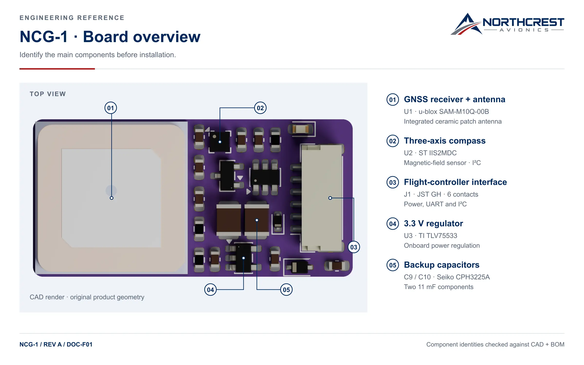
What the five callouts on that sheet identify:
- 01GNSS receiver + antenna — U1 · u-blox SAM-M10Q-00B · integrated ceramic patch antenna
- 02Three-axis compass — U2 · ST IIS2MDC · magnetic-field sensor · I²C
- 03Flight-controller interface — J1 · JST GH · 6 contacts · power, UART and I²C
- 043.3 V regulator — U3 · TI TLV75533 · onboard power regulation
- 05Backup capacitors — C9 / C10 · Seiko CPH3225A · two 11 mF components
Downloads
- NCG-1 datasheet DS-001A2026-09-15Public download not yet available
- NCG-1-D datasheet————
An internal revision does not establish a public release. DS-001 rev A exists as a six-sheet internal edition; it is not published, and the row above says so rather than linking a file that is not there.
Figures
- A—SVG · 8 KB
- A—SVG · 12 KB
- A—SVG · 31 KB
- A—SVG · 81 KB
- A—SVG · 9 KB
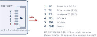
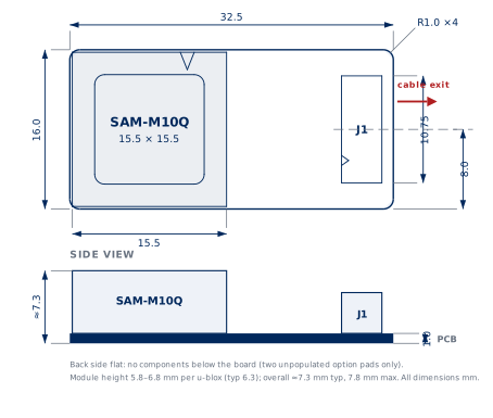
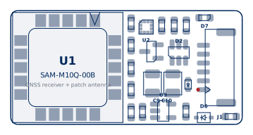
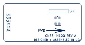
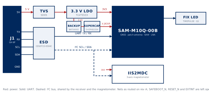
The three reference sheets on this page are not offered as SVG. Their masters embed the board renders and run to several megabytes each; the full-size raster behind each figure's enlarge link is the published form.
Connection

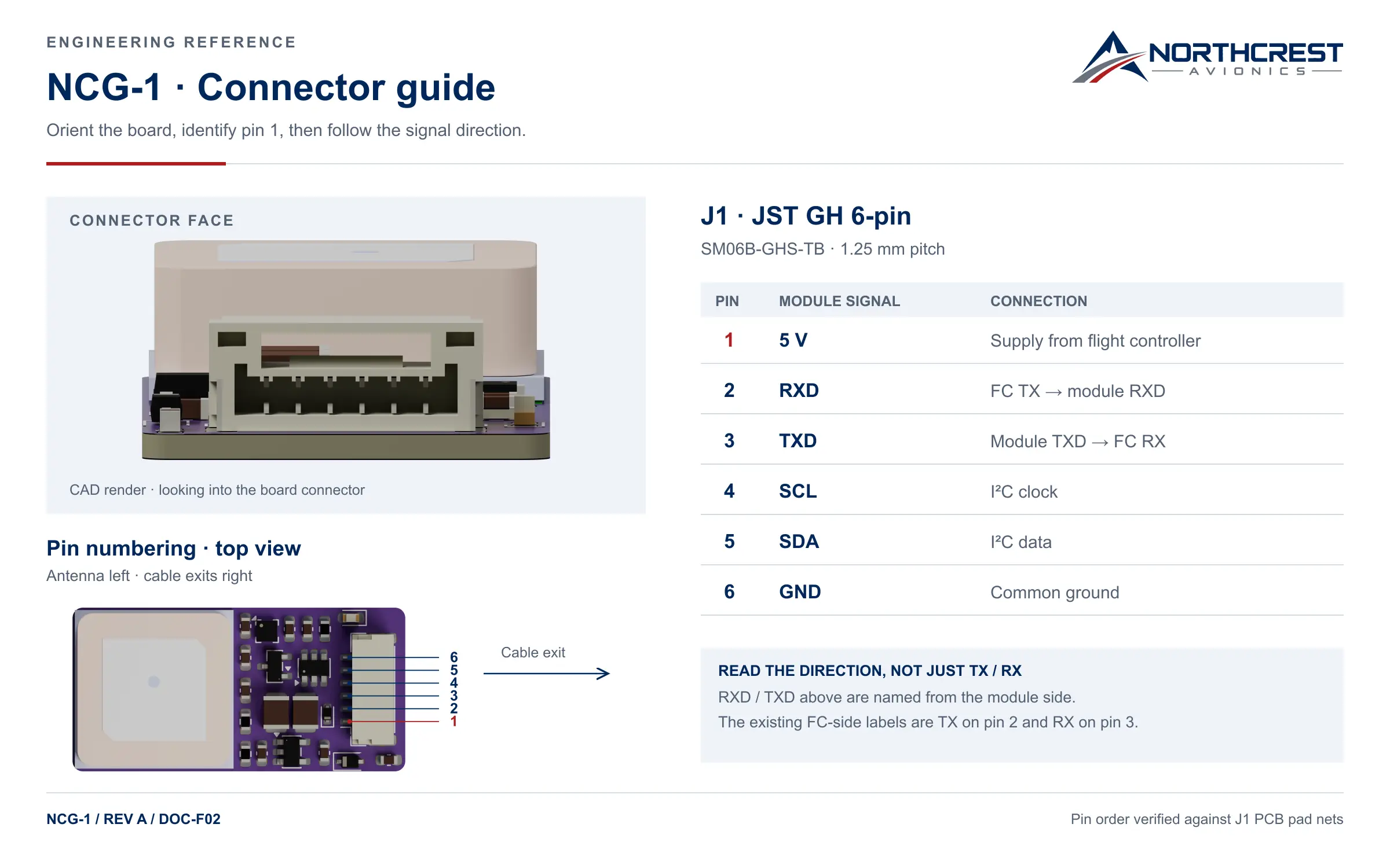
RXD and TXD below are named from the module side. The product pages label the same pins TX and RX from the flight controller's side: pin 2 is the controller's TX and the module's RXD, pin 3 the controller's RX and the module's TXD.
| J1 pin | Module-side signal | Direction / interpretation |
|---|---|---|
| 1 | +5V | Power input |
| 2 | RXD | Module receive; connects to controller TX |
| 3 | TXD | Module transmit; connects to controller RX |
| 4 | SCL | I²C clock |
| 5 | SDA | I²C data |
| 6 | GND | Ground |
Pin numbering comes from the top view. Never infer mating-cable pin order from the connector-face view.
Mechanical integration

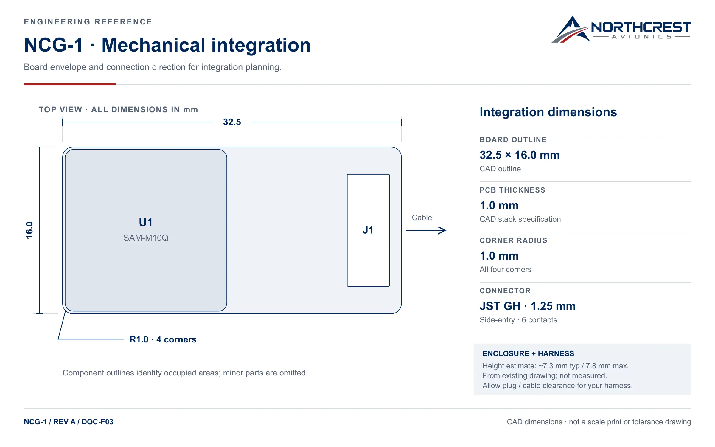
- Board outline
- 32.5 × 16.0 mm
- PCB thickness
- 1.0 mm
- Corner radius
- R1.0 mm · all four corners
- Connector
- JST GH · 1.25 mm · side-entry · 6 contacts
- Overall height
~7.3 mm typ / 7.8 mm max — from the existing drawing, not measured
Plug insertion and bend clearance depend on the mating harness you choose, so no clearance dimension is given here.
This is an integration reference, not a toleranced fabrication drawing or a scale-print template: component outlines mark occupied areas and minor parts are omitted.
Configuration & validation
Firmware defaults
UART 9600 baud · 8N1 · NMEA/UBX
- ArduPilot
- —
- PX4
- —
- Betaflight
- —
- INAV
- —
Per-stack parameters are published after first-article bench test.
Planned bench validation
- 01NMEA output will be checked for presence within 5 s of power.
- 02UBX-MON-VER will be read.
- 03Satellites and C/N0 will be logged over 30 s.
- 04UBX-MON-RF jamming indicators and UBX-NAV-STATUS spoofing-detection state will be read.
- 05Cold-start time-to-first-fix will be recorded (optional, target under 60 s).
No board has been through this yet; it describes the procedure planned for first articles, not a test any unit has passed. Thresholds and results are published when they are measured. The list is written for NCG-1 and its SAM-M10Q receiver; none of it is carried over to NCG-1-D, whose receiver and firmware are different.
Revision history
Document | Document revision | Hardware revision | Publication status |
|---|---|---|---|
| DS-001 · 2026-09-15 · first release | A | A | Public download not yet available |
Document revision and hardware revision move independently. A document revision records a change to the document; it does not establish a public release, and it does not imply a hardware change.
Technical support
Tell us the product, the hardware revision and the integration platform you are working on, and we will send what exists today and say plainly what does not.
Tell us what you are building
Quantity band, target date and program type are enough to start. Lead time is quoted with the contract manufacturer.